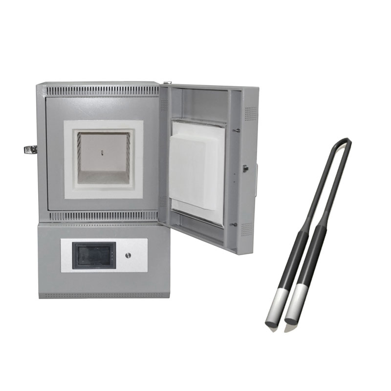
1700 degree muffle furnace of silicon molybdenum rods can be used in furnaces with temperatures ranging from 1600 ° C to 1750 ° C. It is widely used in metallurgy, glass, ceramics, magnetic materials, refractory materials, crystals, electronic components, furnace manufacturing, etc. Ideal heating element for high-temperature sintering of products
1700 degree muffle furnace Featrues
1. LCD touch screen with PID Programmable control
2. CE certified, quality warranty
3. High quality alumina fiber, good heat preservation effect
4. 30 steps Programmable and SCR accuracy temperature control
5. Clear MoSi2 heating element, no color greening changing
6. Low power, energy conservation and environmental protection
muffle furnace Technical parmaters
| Model | CY-M1700-64L |
| Chamber model | Side Door |
| Display | LED or 7” LCD Touch Panel |
| Limiting temperature | 1700℃ |
| Working temperature | ≤1600℃ |
| Heating rate | Suggestion 0~20℃/min |
| Temperature accuracy | ±1℃ |
| Inside chamber size | 400*400*400(mm) |
| Heating element | MoSi2 |
| Thermal couple | B Type |
| Temperature control | PID automatic control via SCR power control |
| Heating curves | 30 steps programmable |
| Chamber material | Alumina Fiber |
| Rated power | 9.5KW |
| Working voltage | AC 380V, 50-60Hz |
| Packing | PLY wood box |
| Accessories | Door stopper 1 pc, glove 1pair, crucible tongs 1pc, manual book |
Installation and editing
1. After opening the package, check if the muffle furnace is intact and the accessories are complete. A typical muffle furnace does not require special installation and needs to be placed flat on a flat floor or shelf. The controller should avoid vibration, and the placement position should not be too close to the electric furnace to prevent the internal components from working properly due to overheating.
2. A thermocouple is inserted into the furnace 20-50mm, and the gap between the hole and the thermocouple is filled with asbestos rope. It is best to use a compensation wire (or an insulated steel core wire) to connect the thermocouple to the control. Pay attention to the positive and negative poles.
3. An additional power switch is required at the power line introduction to control the total power supply. In order to ensure safe operation, the electric furnace and the controller must be reliably grounded.
4. Before use, adjust the thermometer indicator to zero. When using the compensation wire and cold end compensator, adjust the mechanical zero point to the reference temperature point of the cold end compensator. When the compensation wire is not used, the mechanical zero point is used. Adjusted to zero scale, but the temperature indicated is the temperature difference between the measurement point and the cold junction of the thermocouple.
5. After checking the wiring and confirming it is correct, cover the controller casing. Adjust the temperature indicator’s setting pointer to the desired operating temperature and then turn on the power. Turn on the power switch. At this time, the green light on the meter indicates that the green light is on, the relay starts to work, the electric furnace is energized, and the current meter displays current. As the internal temperature of the electric furnace rises, the temperature indicating instrument pointer also gradually rises. This phenomenon indicates that the system is working normally. The heating and constant temperature of the electric furnace are respectively indicated by the traffic light of the temperature indicator, the green light indicates the temperature rise, and the red light indicates the constant temperature.